Launch fiber / Connectors & Terminations
IDIL Fibres Optiques provides launch fiber (spools) with single-mode (SMF) and multi-mode fibers (MMF). Different types and lengths are available both for SMF and MMF.
Launch fiber summary
IDIL Fibres Optiques proposes three types of packaging:
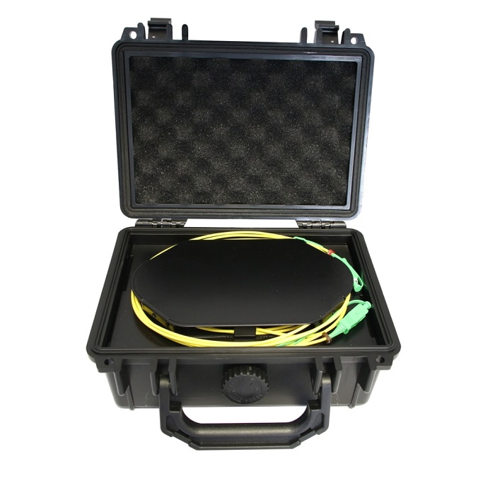
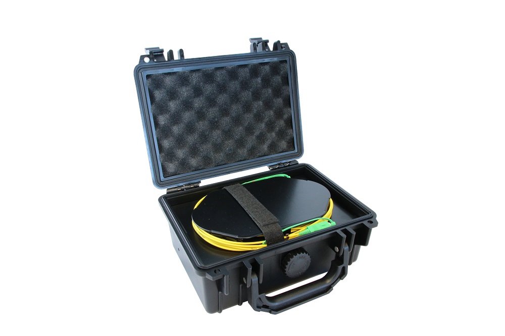
- Launch fiber case : robust & compact.
- Launch fiber cover : very useful & compact
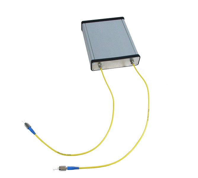
- Launch fiber box (with or without pigtails) : robust & compact.
The cover of launch fiber can easily be put in the cover of a reflectometer.
The OTDR fiber enables easiest transportation of optical fibers that are used for testing applications for example.
Contact us
for more informations
Features
- Customizable length, connector style and fiber type
- High quality protection box
- Low insertion loss
- High reliability and stability
- Compact and rugged
- User friendly packaging solutions
Applications
- Fiber network test applications
- OTDR dead zone
- Insertion loss, reflectance of the near-end connection measurements
- Telecom simulation
- Time delay
Specifications
| FIBER TYPE | |
|---|---|
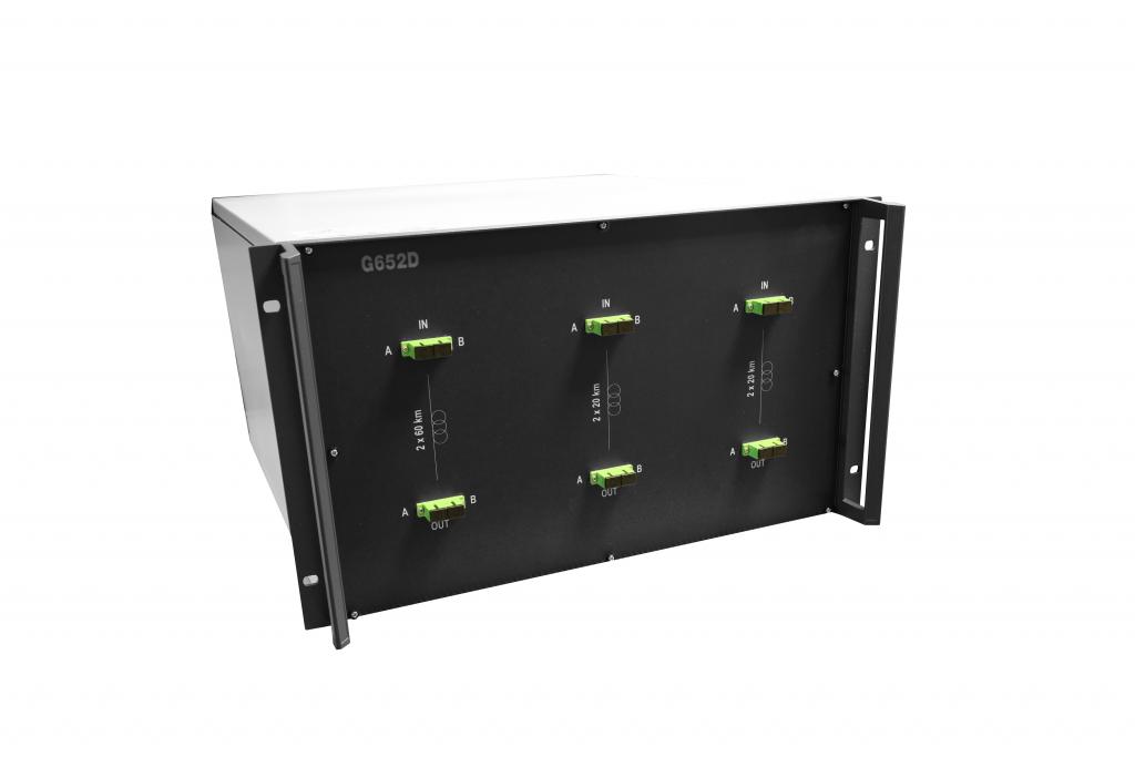
| Singlemode fiber | Type : G652D, G655, G657 A&B |
| Length : 500 m, 1000 m, 2000 m, custom | |
| Multimode fiber | Type : 50/125 (OM2, OM3, OM4), 62.5/125 |
| Length : 150 m, 500 m, custom | |
| DIMENSIONS | |
| Launch fiber case | 210 x 167 x 90 mm³ |
| Launch fiber cover | 150 x 150 x 40 mm³ |
| Launch fiber box (with or without pigtails) | 120x100x30 mm³ |
| 160x120x30 mm³ | |
| CUSTOMIZATION | |
| Fiber type | single-mode, multi-mode |
| Connector | With or without connectors : SC, LC, ST, FC, E2000, others |
| Insertion loss | Depending on fiber type and length. Please contact us. |
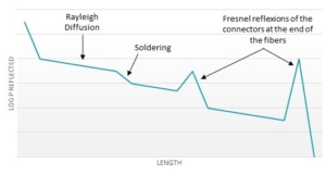
How it works
Also named OTDR fiber, Launch Cable, Receive Cable or Fiber Ring, a Launch Fiber is used to identify faults in the total fiber length. How to use?
- Connect the fiber between an OTDR and the fiber link under test. In this configuration, the loss of the near-end connection can be measured.
- Connect the fiber to the far-end connector of your fiber link under test. In this configuration, the loss of the far-end connection can be measured.